
)


48KXMA8004
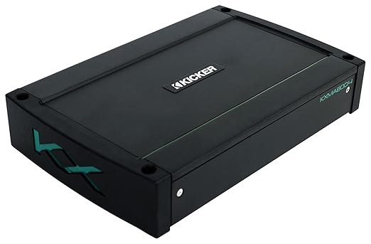
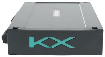
Marine Amplifier: The Kicker KXMA800.4 (48KXMA8004) is a 4-channel marine amplifier, effectively two 2-channel amplifiers built into one chassis (labeled Amp1 and Amp2). Any pair of channels can be bridged, so it can be configured to power 4-channels, 3-channels, or 2-channels. The KXMA series amps are designed for the marine environment and include ABYC/NMMA-compliant power and ground terminals, anti-corrosive inputs and outputs, gasket protected controls, conformal-coated circuit boards, stainless-steel mounting screws, and a UV-treated aluminum chassis.
Note: Keep in mind, marine amplifiers are not waterproof, and should not be mounted where they will likely get wet.
Class D Amplification: This amp features a Class-D design, efficiently providing ample power in a compact chassis. The power output is as follows:
- 100 watts RMS x 4 into 4 Ohms (1 kHz, @14.4V, ≤ 1% THD+N)
- 200 watts RMS x 4 into 2 Ohms (1 kHz, @14.4V, ≤ 1% THD+N)
- 400 watts RMS x 2 into 4 Ohms bridged (1 kHz, @14.4V, ≤ 1% THD+N)
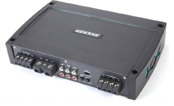
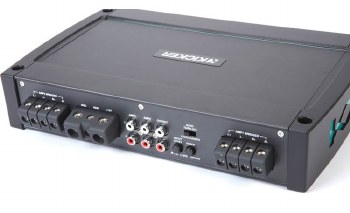
Controls & Indicators:
- Input Level: 2-position switch; select High (speaker-level) or Low (line-level)
- Fader: On/Off switch; used to set the number of input channels connected; Off-Amp1 input feeds all channels; On-each amp's input will be independent
- Auto Turn-on: one 3-position switch:
- +12V: amp turns on when +12 volts is supplied to the remote (REM) terminal on the amp (preferred method)
- DC Offset: amp turns on when it sees the DC Offset voltage from a speaker-level input signal (typically the second best option)
- Audio (Signal Sense): amp turns on when it detects audio from a speaker-level input signal (input gain must be set correctly for this method to work)
Note: If using either the DC Offset or Audio methods of powering the amplifier On/Off, the REM terminal becomes a +12V output that can be used for activating additional amplifiers.
- Protection LED (PRT): red Protect LED indicates a problem:
- Flickering: indicates low-voltage from the battery, either from a low battery or a weak power/ground connection
- On Solid: indicates overheating, shorted speaker output, or voltage not in the 10-16 volt range
Amp1 Controls: Amp1 and Amp2 have independent controls:
- Input Gain: rotary dial; continuously variable from 125mV to 5V with the Input Level switch set to Low; 250mV to 10V with the Input Level switch set to High; each gain control has an LED backlight to indicate the signal is clipping
- Crossover Switch: 3-position switch; select Off, High Pass, or Low Pass; the slope is 24dB/octave
- Frequency: rotary dial; range depends on Frequency Range switch; continuously variable from 10-500 Hz (x1), or 100-5,000 Hz (x10)
- Frequency Range: 2-position switch; sets the frequency range for the filter to x1 or x10
- KickEQ+ Bass Boost: rotary dial; increase the bass level between 0dB and +6dB; centered at 40 Hz
Amp2 Controls:
- Input Gain: rotary dial; continuously variable from 125mV to 5V with the Input Level switch set to Low; 250mV to 10V with the Input Level switch set to High; each gain control has an LED backlight to indicate the signal is clipping
- Crossover Switch: 4-position switch; select Off, High Pass, Low Pass, or Bandpass; the slope is 24dB/octave
- HP Frequency: rotary dial; continuously variable from 10-500 Hz
- LP Frequency: rotary dial; range depends on Low-Pass Range switch; continuously variable from 40-500 Hz (x1), 400-5,000 Hz (x10)
- Low-Pass Range: 2-position switch; sets the frequency range for the low-pass filter to x1 or x10
- KickEQ+ Bass Boost: rotary dial; increase the bass level between 0dB and +6dB; centered at 40Hz
Wire Connections: The KXMA800.4 has screw-down terminals for the power, ground, turn-on (REM), and speaker outputs. The Power and Ground terminals accommodate up to 4-gauge wire (which Kicker recommends) and the remote and speaker terminals accommodate up to 8-gauge wire. The power and ground terminals are ABYC/NMMA compliant for marine installations.
Fuse: The amplifier doesn't have a fuse on the chassis, therefore a 100-amp fuse must be installed in-line on the power wire next to the battery.
Note: Currently Kicker will extend the standard warranty by an additional year (for a total of three years) when a qualifying Kicker installation kit is purchased with the amplifier.
Input Signal: The amp accepts either high (speaker-level) or low (line-level) voltage input signals on the two pair of RCA inputs, selectable using the input level switches on the side of the amp. When using a speaker-level input signal, add the optional Kicker KiSL speaker-level to RCA adapter (sold separately). The input sensitivity is 0.125-5 volts (low) or 0.25-10 volts (high).
Line Out: A single pair of RCA Output jacks is provided as a "pass-thru" for the incoming signal, letting you run the signal out to additional amplifiers.
Dimensions:
- Width: 11.58"
- Height: 2.19"
- Depth: 8.26" (8.78" including wire)
- 4-channel marine amplifier
- 100 watts RMS x 4 at 4 ohms (200 watts RMS x 4 at 2 ohms)
- 400 watts RMS x 2 bridged at 4 ohms (4-ohm stable in bridged mode)
- Class D amp technology
- gain knobs also function as clip lights
- Amp 1:
- variable high- or low-pass filter (10-500 Hz, 24 dB/octave); 10x switch
- Amp 2:
- variable high-pass filter (10-500 Hz, 24 dB/octave)
- variable low-pass filter (40-500 Hz, 24 dB/octave); 10x switch
- bandpass engages both high- and low-pass filters
- variable bass boost (0-6 dB at 40 Hz) on all channels
- weather-resistant conformal-coated circuit boards
- front-mounted controls protected behind gasket-sealed fold-down door
- Fail-Safe Integration Technology eliminates noise from your vehicle's electrical system
- preamp and speaker-level inputs (speaker wire to RCA adapter required for speaker-level input)
- wiring, hardware, and fuse not included with amplifier
- 4-gauge power and ground wires and a 120-amp fuse recommended
- dimensions: 8-5/16"W x 2-1/8"H x 11-9/16"D
Support
![]()
Manuals
2021 KXMA Stereo | Multilingual - Download
2021 KXMA Stereo Info Card | Multilingual - Download
![]()
Support Links
Amplifier Power Testing
Subwoofer / Speaker FAQ
Box Building Help
Wiring Diagrams
Reviews
Add-ons


Share:
Share on Facebook Share on Twitter Share on Pinterest Tell a friend