

)


KICKER
47KEYLOC
KEYLOC Smart Line-Out Converter, built-in DSP, KIT2 Technology; 5-1/2" L x 1-3/8" H x 2-3/4" W: RoHS Compliant
Overview: The Kicker KEYLOC is a 2-channel line-out converter with DSP processing that can detect, analyze, and correct the audio from you factory system, when adding aftermarket amplifiers. The KEYLOC's patent-pending KEY algorithm automatically detects and analyzes crossovers, EQ, time delay, and any all-pass filters present. It will then correct these various audio treatments, for the smoothest frequency response possible, and level-matches the left and right audio channels, giving you a clean, uncolored audio signal for your aftermarket amplifiers.
DSP Features: The KEYLOC's 2-channel DSP processing includes the following features:
- Automatic Turn-On: The KEYLOC senses DC offset on the speaker-level inputs, between 2.5V and 6V, to automatically power on. A Remote In wire can be used if the connected headunit features a turn-on output. The KEYLOC features a corresponding Remote Output wire that can provide a +12V output signal to power on other equipment.
- Frequency Response Correction: Smoothes the frequency response on the 2 input channels via EQ correction, with Q's ranging from 0.5 - 10 with up to ±12dB of boost or cut.
- Factory Time Delay Defeat: Ranges from .06mS - 10mS, with .06mS accuracy.
- All-Pass Filter Defeat: The KEYLOC can correct up to 3 all-pass filters on one channel. The all-pass filters can even have a Q ranging from 0.5-3.5, as long as they're not interacting with other all-pass filters.
- Passive Frequency Detection: The KEYLOC's default status is in Passive Frequency Detection mode which can detect what band of frequencies are available on each of the speaker input channels.
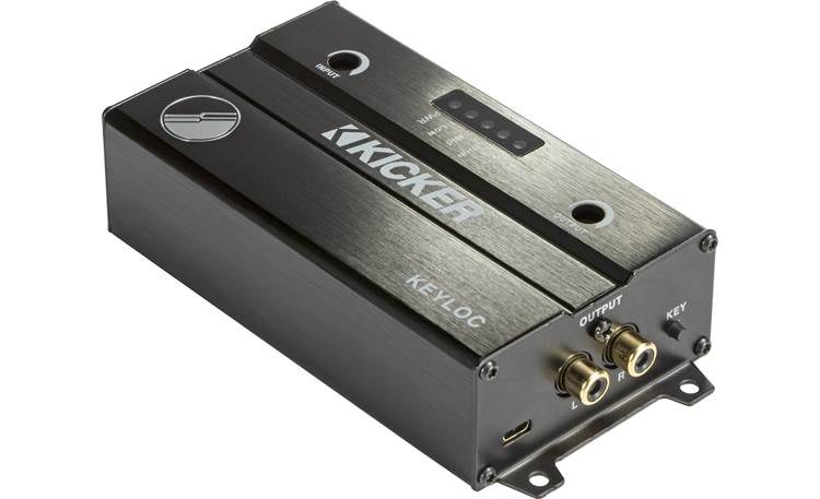
Signal Identification & Restoration: The KEYLOC setup process includes playing various test tones through the system for analysis and correction. Test tones for the converter are not included and can be found here. Three top-panel LEDs, Low, Mid, and High, can show what frequencies have been detected for each channel, using the downloaded Pink Noise track:
- Low: 20Hz - 200Hz
- Mid: 200Hz - 2kHz
- High: 2kHz - 20kHz
Notes:
- Pink noise test tones are NOT included and can be downloaded here.
- Factory noise-canceling and active noise enhancement must be disabled before running the Auto-Setup.
Signal analysis and restoration are completed using the downloaded GainMatchSweep, Noisefloor, and FullTest test tracks. These are custom audio files that, when played from your headunit, will allow the KEYLOC to determine what frequency, coloration, and staging corrections to make. When completed, the KEY button will let you toggle between the original sound and the corrected sound, for a quick A/B comparison. It's also used for navigating through the setup, menus, and for resetting the module back to default. When the automatic setup is complete, the following Menu options are provided via the top-panel LEDs:
- LED 1: All-pass or Time-Delay defeat On/Off.
- Solid: Time-Delay correction is active.
- Blinking: Time-Delay & All-Pass are defeated.
- LED 2: Indicates if Left/Right channel gain matching is On (solid) or Off (blinking).
- LED 3: Reset (hold KEY button for 10 seconds).
- LED 4: Exits the Menu (hold KEY button for 1 second).
Additional Controls, Indicators and Wiring:
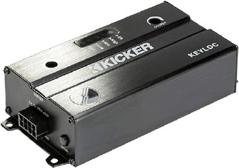
- Input Sensitivity (Hi/Lo): This 2-way push-button lets you select the input signal range. If the signal is coming from a factory headunit, the Lo setting should be used. If connecting to the output of a factory amplifier, the Hi range should be used.
- Lo: Accepts signals ranging from 125mV - 10V. This setting incorporates a 60Ω load on the input, allowing it to be used with factory radios that would normally stop outputting sound when no speaker is detected on the wire.
- Hi: Accepts signals ranging from 1V - 40V.
- Input Gain: Used to fine-tune the input signal level once the Input Sensitivity range has been selected.
- Output Gain: Adjusts the converted signal level passing from the RCA output jacks.
- Power LED: Lights when the processor is powered on.
- EQ LED: Indicates when the processor is passing a corrected signal to the output (LED on), or when the correction is defeated (LED off). This can be toggled on/off with the KEY button.
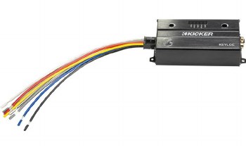
Wiring: An 8-pin Molex connector includes the following wires:
- Yellow: Connects to a +12V constant power source. This line should be protected with a 2A fuse (not included).
- Red: Remote turn-on input.
- Blue/White: Remote turn-on output.
- Black: Chassis ground.
- White: Left front speaker input (+).
- White/Black: Left front speaker input (-).
- Gray: Right front speaker input (+).
- Gray/Black: Right front speaker input (-).
Outputs: Two female RCA jacks provide the audio output, with up to 10Vrms of signal strength.
Mounting: The Kicker KEYLOC module can be mounted using the 4 screw-hole tabs and the provided hardware, or using standard wire-ties (not included). Its compact size allows it to be mounted in most dashes or tight compartment spaces.
- 2-channel active line output converter
- automatic frequency response detection (RTA)
- automatic factory EQ correction (DE-EQ)
- download test tones and tracks from Kicker.com/test-tones
- manual programming includes an all-pass option to remove factory phase issues
- 2 speaker-level inputs with up to 400 watts RMS power handling
- 2 preamp-level outputs (up to 10V)
- output gain controls
- 12-volt turn-on lead output
- fuse rating: 2A x 1
- dimensions: 5-3/4"W x 1-7/16"H x 2-7/8"D


Share:
Share on Facebook Share on Twitter Share on Pinterest Tell a friend